Flow measurement using Orifice Assembly with Differential pressure Transmitter
Flow measurement using Orifice Assembly with Differential pressure Transmitter
Flow measurement using Orifice assembly is one of the most common and cost-effective Solution used across various industries for clean liquids, gases, steam, low viscous liquids flowing in a frictionless pipe.
In this blog, let us look at the Orifice working Principle with differential
Orifice – working Principle:
Orifice works on Bernoulli’s principle.
Bernoulli’s Research was to find the relation between pressure, kinetic energy, and gravitational potential energy of a fluid in a closed container or pipe.
Bernoulli’s theorem states that the speed or velocity of the process medium (here, liquid or gas) increases with decrease in pressure or decrease in the fluid’s potential energy and vice versa. However, the total energy remains the same in the entire closed pipe.
Example for Bernoulli’s theorems in our day-to-day life
- Dynamic lift on the wings of an aeroplane.
- Swinging of a spring cricket ball.
- Roof of thatched houses that fly away during cyclones.
- Perfume spray from the bottle.
How is the Volumetric Flow (Q) calculated from Bernoulli’s equation?
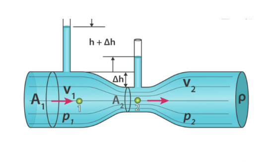


Fluid density(ρ), Acceleration due to gravity(g), Height at elevation (h1&h2) are constant.The variables are pressure, velocity ( P1,V1,P2,V2).
To settle this Equation, let us use Law of Continuity which is Q=A1V1=A2V2
By Equalling this, final Q(Volumatic flow) derivation as below.

What is orifice and how looks?
A hole or opening in the body of the metal plate is called Orifice as shown in the picture.

Overview of Working of orifice plate:
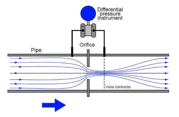
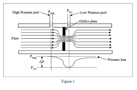
Below is the flow diagram to explain how differential pressure is created using an orifice plate.
By correlating the Bernoulli’s theorem,
“When the pressure increases (in the figure 1 before orifice hole-Normally High-pressure side) the velocity will be low, when the pressure is low (After the flow passes the orifice hole-Normally Low-pressure side) the velocity will be high. The point where the velocity is at maximum called “vena contracta”
Purpose of Differential pressure Transmitter?
To recall the Formula Q=K√DP, it is important to measure “differential pressure” and Perform “Square root” of measured DP to measure the Volumetric Flow “Q”.
The DP Transmitter is used to measure the pressure difference between P-high and P-low (in figure 2) and In- built transfer function helps to do square root of the measured differential pressure.

How the Square is calculated?
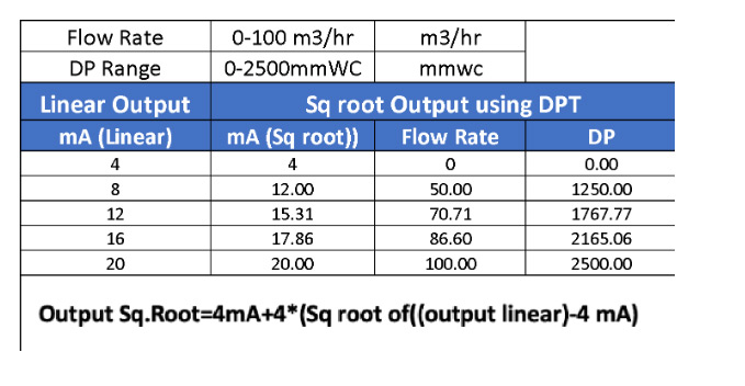
Below is the example clarifying the difference between Linear and square root output. Square is arrived at using the formula given below which shall be configured against the flow measureing rate.
